Photos of the CHAMP Intense Pulsed Ion Beam
B.P. Wood
(P-24), bwood@lanl.gov, (505)665-6524
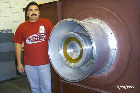 Inside of the vacuum
system, showing the anode. The yellow ring is the "fast coil", potted in
epoxy, which produces the plasma from gas puffed in on axis. The ion beam is
extracted from this plasma. The brown structure to which the anode is attached is
the oil tank which will house the high voltage components. Technician Darrell Roybal
is pictured.
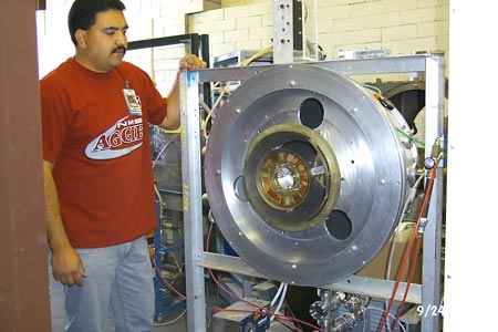 The cathode, which
bolts onto the anode shown in the previous picture. The yellowish rings are
the "slow coils" which produce the radial magnetic field which prevents
electrons from crossing the anode-cathode gap and shorting it out. The conical
cathode rings are between the slow coils.
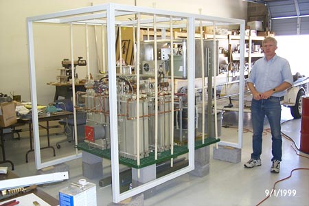 The CHAMP Blumleins, hot
deck, and output transformer in its supporting cage, during construction at TMI, Inc.
This whole structure will sit in the 1750 gallon oil tank. The oil provides
electrical insulation. The capacitors (30" tall white "boxes" on the
left) are charged to 60 kV. Combined with some inductors (difficult to see in this
photo), they form the four parallel Blumlein transmission lines. The hot deck
(silver box near the top of the right-hand side of the structure) contains the power
supplies and triggering mechanisms for the puff valve and fast coil. This box will
float up to 240 kV with the anode during a shot. The 4:1 voltage step-up transformer
is just visible below the hot deck. Dan Petmecky, president of TMI, is pictured.
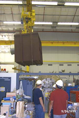 Transporting the CHAMP
oil tank to its laboratory.
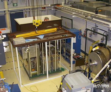 CHAMP sitting outside its
oil tank, for high voltage testing. If this looks like a tight fit in the lab, wait until
we surround the anode assembly with a couple dozen two-ton concrete blocks for x-ray and
neutron shielding!
Return to Applied Plasma Technologies homepage
Return to P-24 homepage
 Inside of the vacuum
system, showing the anode. The yellow ring is the "fast coil", potted in
epoxy, which produces the plasma from gas puffed in on axis. The ion beam is
extracted from this plasma. The brown structure to which the anode is attached is
the oil tank which will house the high voltage components. Technician Darrell Roybal
is pictured.
 The cathode, which
bolts onto the anode shown in the previous picture. The yellowish rings are
the "slow coils" which produce the radial magnetic field which prevents
electrons from crossing the anode-cathode gap and shorting it out. The conical
cathode rings are between the slow coils.
 The CHAMP Blumleins, hot
deck, and output transformer in its supporting cage, during construction at TMI, Inc.
This whole structure will sit in the 1750 gallon oil tank. The oil provides
electrical insulation. The capacitors (30" tall white "boxes" on the
left) are charged to 60 kV. Combined with some inductors (difficult to see in this
photo), they form the four parallel Blumlein transmission lines. The hot deck
(silver box near the top of the right-hand side of the structure) contains the power
supplies and triggering mechanisms for the puff valve and fast coil. This box will
float up to 240 kV with the anode during a shot. The 4:1 voltage step-up transformer
is just visible below the hot deck. Dan Petmecky, president of TMI, is pictured.
 Transporting the CHAMP
oil tank to its laboratory.
 CHAMP sitting outside its
oil tank, for high voltage testing. If this looks like a tight fit in the lab, wait until
we surround the anode assembly with a couple dozen two-ton concrete blocks for x-ray and
neutron shielding!